Mehmet Emre Doğan
Modelling Emax RS2205 Drone Motor on MATLAB
Introduction
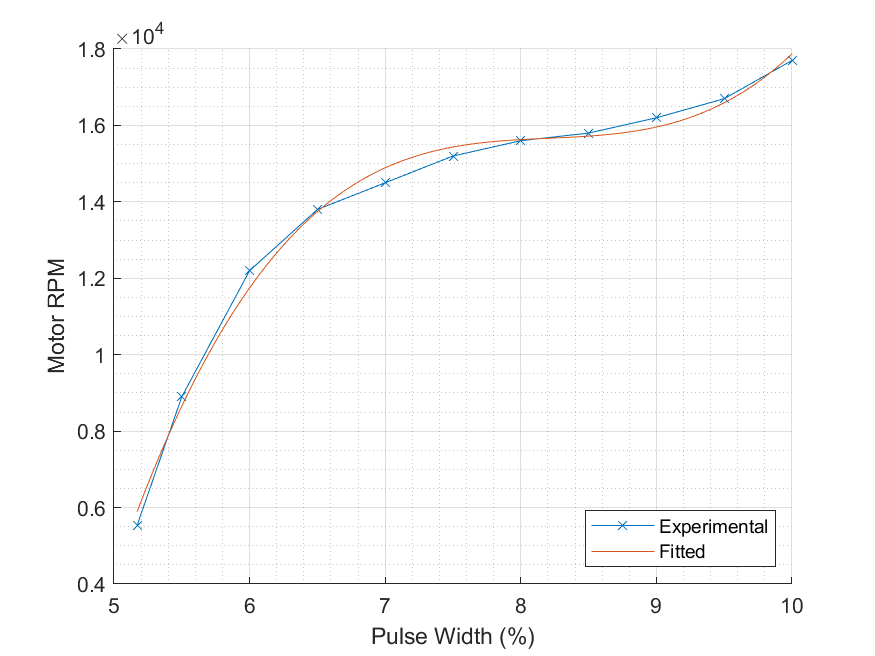
In this blog post, the pulse-width of the applied control signal vs RPM characteristics of Emax RS2205 Drone Motor will be modeled on MATLAB.
Background Information
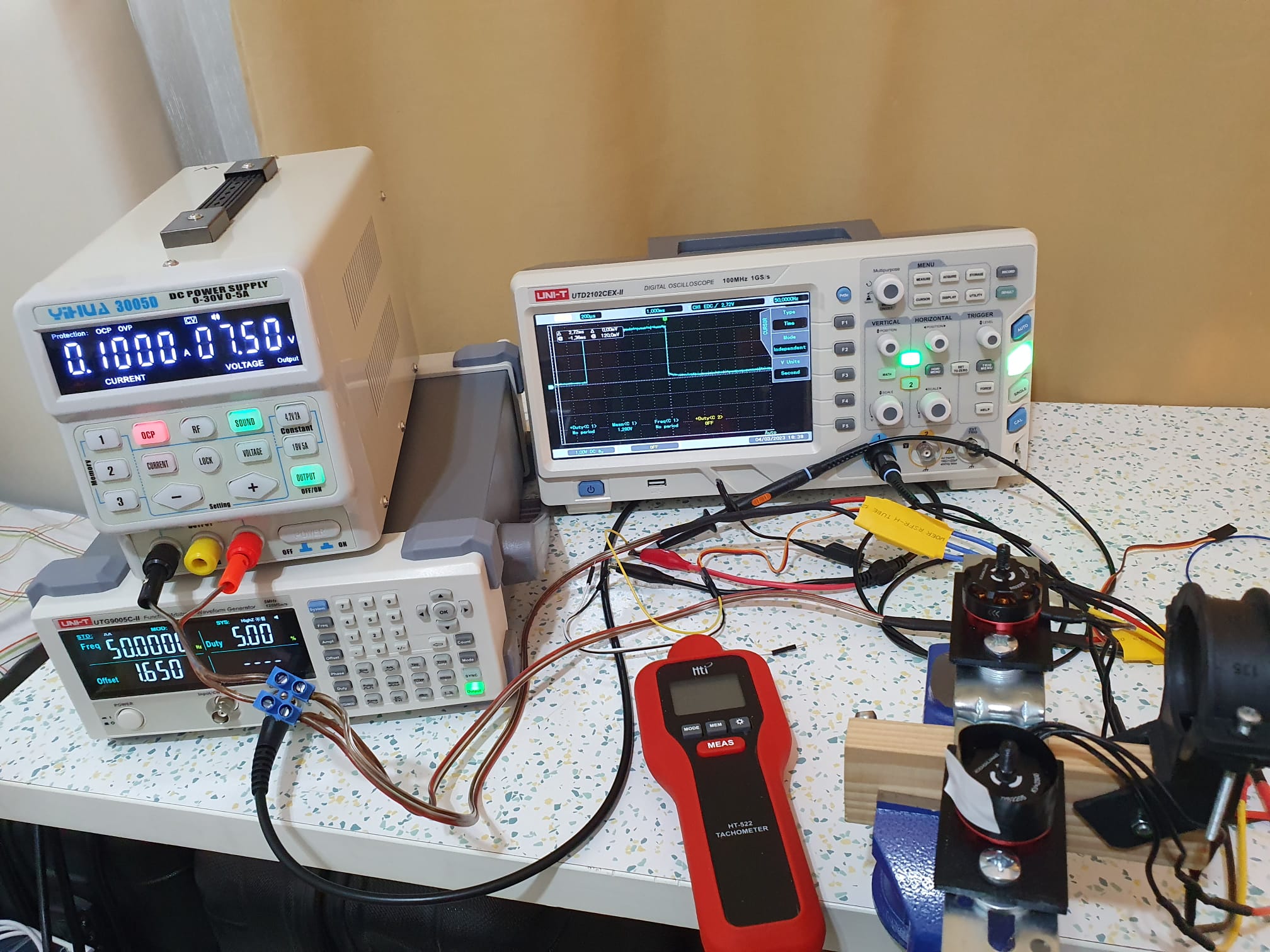
The drone motors are BLDC (Brushless DC) motors. They are, in fact, synchronous AC machines. BLDC motors are driven using the circuit called ESC (Electronic Speed Controller). The used ESCs are the yellow rectangular devices in Figure 1.
A generic ESC requires a pulse waveform of 50 Hz for the control signal. This value is the same as for the hobby servos, like Tower Pro MG995. Altough it is possible to change, the 1 ms pulse corresponds to the OFF state whereas 2 ms pulse corresponds to the maximum speed by default.
A laser tachometer sends a laser beam to the device under test. Then counts the reflections from the device to measure its rotational speed. For the best result, the rotor should be coated with a black colored material to make sure no unwilled reflections take place. Moreover, a small bit of white material is glued on top of the black piece for the reflections.
Experimental Methodology
- Calibrate the ESCs
- Adjust the pulse width in percent using the signal generator
- Verify it using the oscilloscope
- Measure the RPM using the tachometer
- Record the data to MATLAB
Videos
Matlab Code
code.mlx
Result
After the experimental procedure, the graph in Figure 2 is obtained.